Assembly - Putting it all together
In the previous section we covered all the parts that we will need.
In case you missed it, take a quick look here and then come back.
What goes in what goes out?

Our DIY dry box is designed to have the following components INSIDE the dry box enclosure:
- Heater
- Heater Sensor
- Fan
- Internal temperature and humidity sensor
All of the above components need to be attached to their terminal connectors that are located on the DryBox v2 PCBA.
The DryBox v2 PCBA has to be on the OUTSIDE of the dry box enclosure.
This means that all of the components from the above list will have to have their wires passed from the inside to the outside of the dry box.
Usually you would have a small hole (or drill one) for cables to pass through the enclosure. And ideally once the cables are through, you can cover the opening with thermally insulating tape (ie Aluminium tape) to prevent heat leaking from the inside of the enclosure.
Heat leaking
Make sure that you minimize heat leaking/escaping your dry box enclosure.
This heat leaking can affect the external temperature and humidity readings.
Ideally you would want to insulate and/or place the DryBox v2 PCBA further away from the heat of the dry box enclosure.
Fit check first saves time later on!
In the next steps we are going to 'connectorize' (attach wires to terminal plugs) various components. Depending on the size of the opening on your dry box enclosure, the terminal plug may not be able to fit through.
In this case you can feed the wires through the opening first (without the terminal plug) and then attach them to the terminal plug.
Also make sure that all of your components and wires can, not only fit nicely through the opening, but also that you have enough room to wire everything properly, do cable management, keep things away from the heater so they don't melt, open/close the enclosure without cables getting in the way etc.
Heater and Heater Sensor
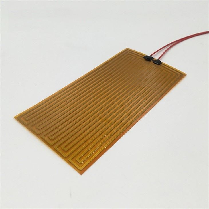
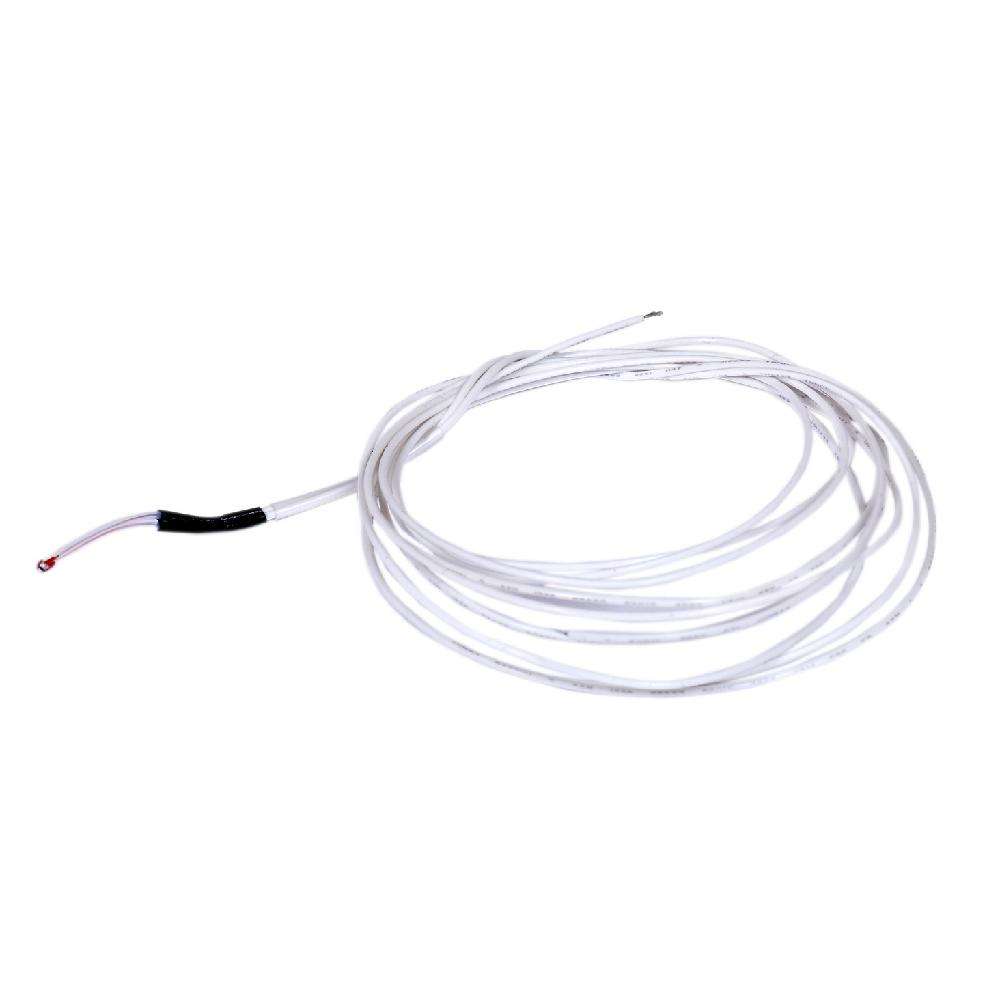
Putting on terminal connectors
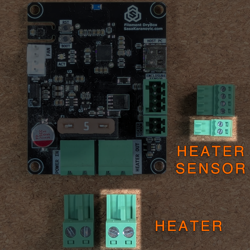
Both the heater and the heater (NTC) sensor need to be connected to the terminal connectors. Using the wire strippers, cut the insulation off the each cable and insert them into their respective terminal connectors.
Make sure you are attaching them to the terminal properly and that there are no wires or wire strands exposed or touching both contacts.
You could optionally use ferrules to crimp the cable first and then connect it to the terminal.
Heater and Heater Sensor Polarity
Despite having + and - signs on the DryBox v2 PCBA, the actual polyimide heater and the NTC heater sensor are not polarized. This means that you can connect them to the terminals either way, they will work, so for these two you do not have to worry about the polarity.
However for other components in this build polarity is going to be very important.
The Heater uses the bigger 2-pin 5.08mm/0.2in pitch terminal plug and the heater sensor uses the smaller 2-pin 2.54mm/0.1in pitch terminal plug.
Attach the Heater and the Heater Sensor
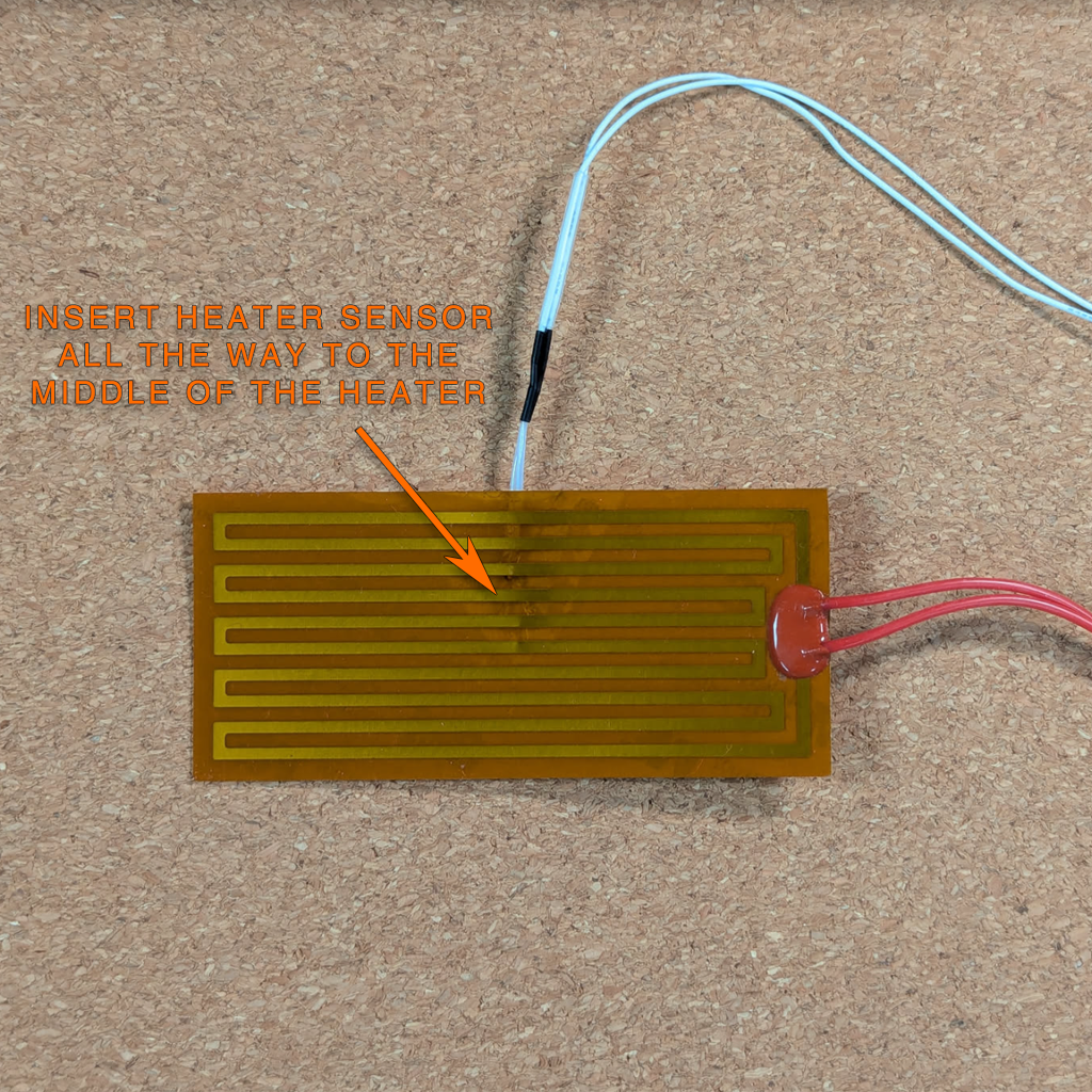
It is very important that the heater sensor is as close as possible to the actual heater and touching the heater. Ideally you would want it placed roughly in the centre of the heater.
This will ensure correct temperature measurement and proper control over the heater temperature.
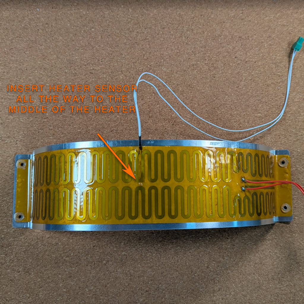
You can use a piece of metal and attach the heater onto it. This should help the heater radiate the heat more efficiently.
Make sure that the heater sensor is sandwiched between the heater and the metal it's attached to. Also make sure that the sensor has a good contact with both the heater and the metal!
Fire hazard
The heater can get really hot! This is a potential fire hazard!
Make sure that you have securely installed the heater and the heater sensor!
Make sure that heater is not in contact with flammable material or anything else that could catch fire or melt when exposed to high temperatures.
Internal temperature and humidity sensor
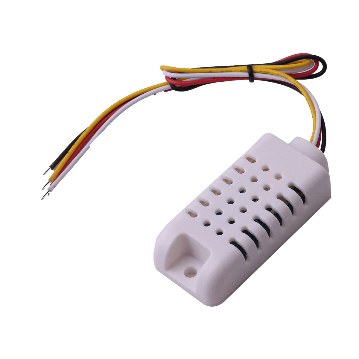
SHT30 is used to measure the internal temperature and humidity inside the dry box.
In order to connect this sensor to the dry box, we need to connect four sensor wires to the terminal plug.
SHT30 uses the smaller 4-pin 2.54mm/0.1" terminal plug.
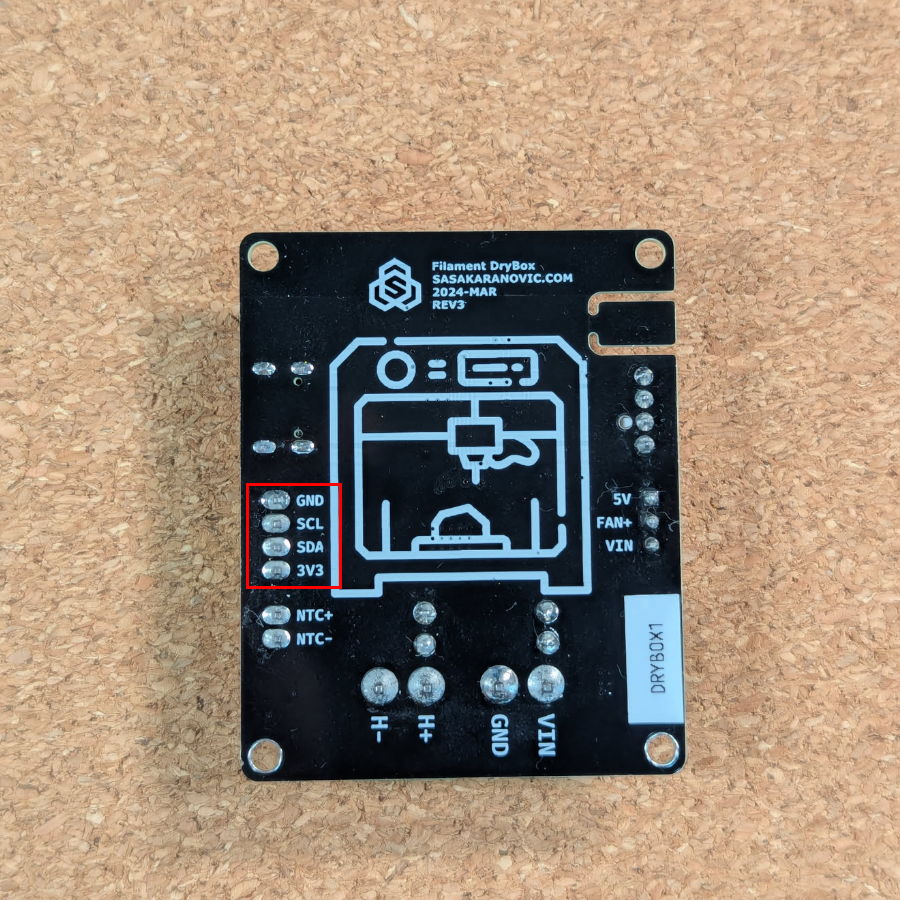
When wiring the SHT30 terminal plug, please follow the labels on the back of the DryBox v2 PCBA and make sure sensor connection matches the terminal connection.
SHT30 Polarity
SHT30 sensor has four connections that are usually marked as 3V3, GND, SDA and SCL.
Wiring them properly is very important, otherwise the sensor might not work properly or it can cause permanent damage to the sensor and/or the board!
On the DryBox v2 PCBA, each pin is labeled on the back of the board and the 4-pin terminal connector is keyed/polarized.
Fan
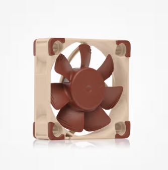
The fan needs to be installed inside the dry box enclosure. If the fan cable is too short to reach the DryBox v2 PCBA, you can use a fan cable extender.
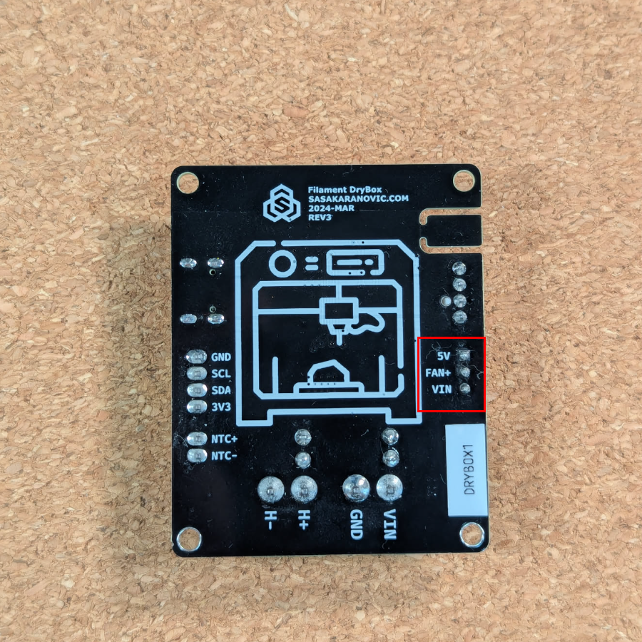
On the DryBox v2 PCBA right below the 4-pin fan connector, there is also a 3-pin header that is used for fan voltage selection.
Place the jumper onto this header to select if your fan should be powered from the 12V (VIN) or 5V rail.
Installation
The heater, heater sensor, inside temperature and humidity sensor and the fan need to be installed inside the dry box enclosure.
There are multiple ways to do this and they will greatly vary depending on which parts you are using and your dry box enclosure.
Fire hazard
Please pay close attention and make sure that everything inside your dry box is secured and installed safely.
Double check that there are no melting or fire hazards!
Connecting everything to the DryBox v2 PCBA
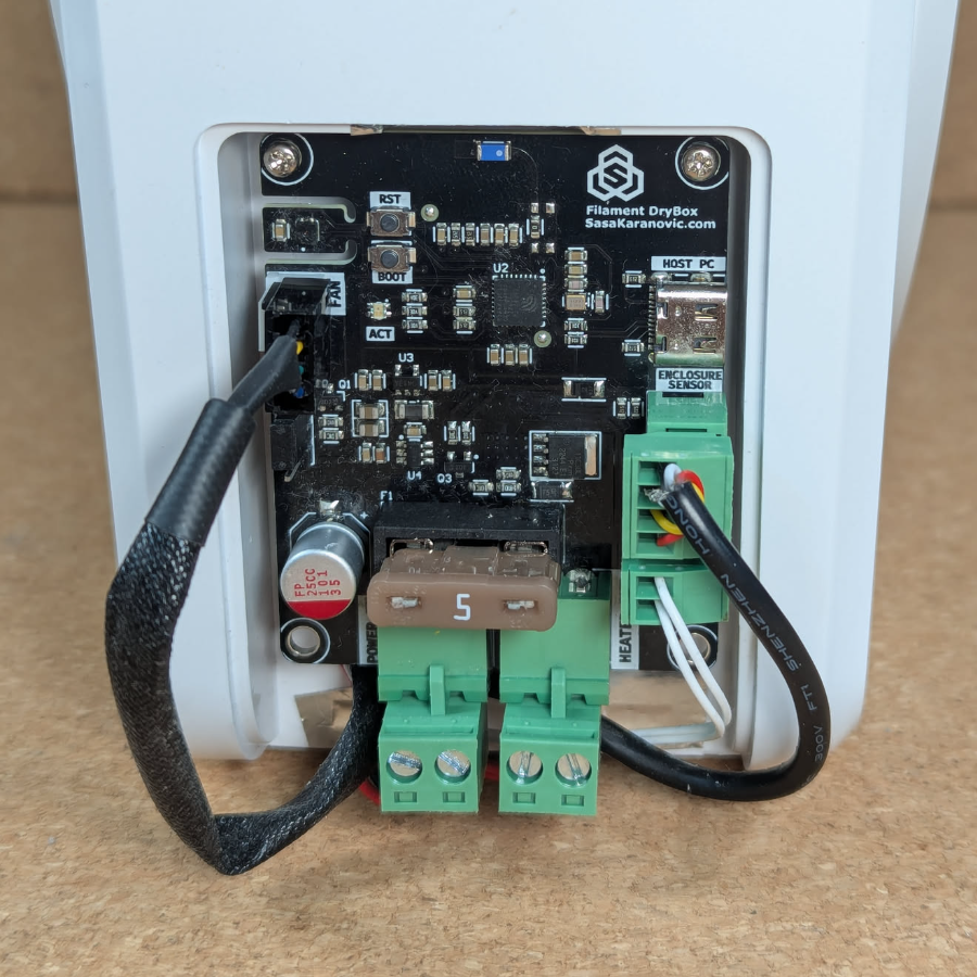
Once everything is installed inside the dry box enclosure, you should be able to connect all the terminal plugs and the fan to your DryBox v2 PCBA.
We still need to load the firmware and test heater protection for which you will need access to the USB connector and the heater sensor terminal plug.
So maybe hold off on fastening/securing the PCBA into place until we are finished with these steps.
Now that everything is neatly installed and ready to go.
We can go ahead and load up the firmware.